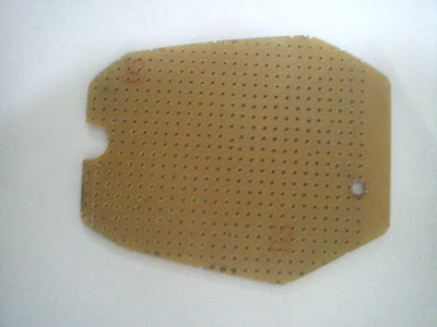
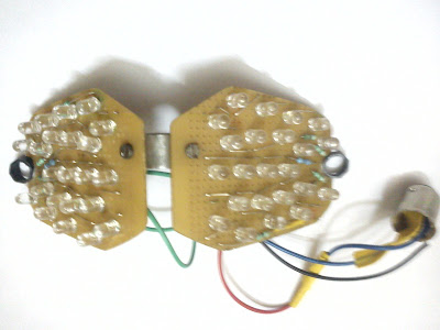
A new product for your vehicles. 0.3 Watt LED indicators.
I will post a video soon...
Hobby Circuits
Thursday, January 30, 2014
Monday, February 25, 2013
Water level monitor using transistor based sensor
Recently, I had built a water level monitoring setup at my home. I used transistors to sense the water level instead of using a mechanical sensor to avoid wear and tear due to prolonged usage. The main unit is based on a PIC16F886 microcontroller. The microcontroller is used to convert the analog signal from the sensor into a digital value to control the water pump. The percentage of water is then displayed through 7 segment displays.
COMPONENTS USED:
1) General purpose PCB
2) Transistors
- BC547B x 24pcs
3) PIC16F886 microcontroller
4) IC 7447
5) IC 7805
6) 7 segment displays -> 3pcs
7) Resistors
- 330 x 7pc
- 4.7K x 1pc
- 5.6K x 1pc
- 10K x 2 pc
- 22K x 3pcs
- 330K x 20pcs
8) Relay 250V 20A
9) Capacitor
-10uF x 1pc
10) DC regulated power supply (Around 9V)
11) PVC pipe (to mount the sensor)
12) Casing for main unit
13) Power socket and plug
14) Lots of wires!
SENSOR:
This sensor measures water level in 20 discrete levels. Hence, 20 transistors are required, one for each level.
Each bolt is connected to the base of a sensor transistor. The voltage reference is connected to the bottommost bolt.
One single unit of sensor looks like this:
When the water level rises, an electric contact is made between the reference bolt and some of the bolts in the the sensor array, and turns on the corresponding transistors. The number of transistors which are switched on can be determined by measuring the sum of emitter currents.
The schematic of the complete sensor:

CONTROL UNIT:
The PIC16F886's ADC is used to convert the sensor's analog values to digital value. The percentage of water is displayed on three 7 segment displays. The motor is switched on when the water percentage drops below 35% and switched off when the water level rises above 95%.
Pictures of the control unit being mounted into its casing:
The values obtained from the sensor are not exactly linear because a precision summing circuit is not used. Due to this issue, the output has to be calibrated in code.
The assembly code for the microcontroller:
COMPONENTS USED:
1) General purpose PCB
2) Transistors
- BC547B x 24pcs
3) PIC16F886 microcontroller
4) IC 7447
5) IC 7805
6) 7 segment displays -> 3pcs
7) Resistors
- 330 x 7pc
- 4.7K x 1pc
- 5.6K x 1pc
- 10K x 2 pc
- 22K x 3pcs
- 330K x 20pcs
8) Relay 250V 20A
9) Capacitor
-10uF x 1pc
10) DC regulated power supply (Around 9V)
11) PVC pipe (to mount the sensor)
12) Casing for main unit
13) Power socket and plug
14) Lots of wires!
SENSOR:
This sensor measures water level in 20 discrete levels. Hence, 20 transistors are required, one for each level.
One single unit of sensor looks like this:
When the water level rises, an electric contact is made between the reference bolt and some of the bolts in the the sensor array, and turns on the corresponding transistors. The number of transistors which are switched on can be determined by measuring the sum of emitter currents.
The schematic of the complete sensor:

CONTROL UNIT:
The PIC16F886's ADC is used to convert the sensor's analog values to digital value. The percentage of water is displayed on three 7 segment displays. The motor is switched on when the water percentage drops below 35% and switched off when the water level rises above 95%.
Pictures of the control unit being mounted into its casing:
The values obtained from the sensor are not exactly linear because a precision summing circuit is not used. Due to this issue, the output has to be calibrated in code.
The assembly code for the microcontroller:
;;;;;;;;;;;;;;;;;;;;;;;;;;;;;;;;;;;;;;;;;;;;
;;                                        ;;
;; AUTHOR : ARJUN M NAIR                  ;;
;;                                        ;;
;; DESCRIPTION : WATER LEVEL         ;;
;;                                        ;;
;;                                        ;;
;;;;;;;;;;;;;;;;;;;;;;;;;;;;;;;;;;;;;;;;;;;;

 include

  ORG 0000
  GOTO START

START    ;MAIN PROGRAM START
  ORG 0020
  BANKSEL OSCCON
  MOVLW 61h
  MOVWF OSCCON
; CLKSTABLE BTFSS OSCCON, 2
;  GOTO  CLKSTABLE

    ;PORT B CONFIG
  BANKSEL TRISB
  CLRF TRISB
  BANKSEL ANSELH
  CLRF ANSELH
  BANKSEL PORTB
  CLRF PORTB
    ;PORT A CONFIG
  BANKSEL PORTA
  CLRF PORTA
  MOVLW 0FFh
  BANKSEL ANSEL
  MOVWF ANSEL
  BANKSEL TRISA
  MOVWF TRISA
  BANKSEL ADCON0
  MOVLW 0C1h
  MOVWF ADCON0
  BANKSEL ADCON1
  MOVLW 30h
  MOVWF ADCON1

    ;PORT C CONFIG
  BANKSEL TRISC
  CLRF TRISC
  BANKSEL PORTC
  CLRF PORTC
  BANKSEL PSTRCON
  CLRF PSTRCON


    ;APP INITIATE
  CLRF 73h

 STARTPROC   ;PROCESS WHEN APP STARTS
  BANKSEL ADCON0
  BTFSS ADCON0, 1
  CALL CONVERT
  CALL DISPUPD
  GOTO STARTPROC


;; SUBROUTINES


DISDELAY    ;DISPLAY DELAY FOR BRIGHTNESS (APPROX 5ms AT 4MHz CLOCK)
  MOVLW d'15'
  MOVWF 70h
 LDSD2 MOVLW d'150'
  MOVWF 71h
  LDSD1 DECFSZ 71h, 1
  GOTO LDSD1
  DECFSZ 70h, 1
  GOTO LDSD2
  RETURN

DISPUPD    ;UPDATE THE DISPLAY (1 PASS)
  BCF STATUS, 5 ;FIRST CONVERT TO BCD
  BCF STATUS, 6
  MOVF 73h, 0
  CLRF 22h
  CLRF 78h
  MOVWF 20h
 LDISP1 MOVF 20h, 0
  MOVWF 21h
  MOVLW 0Ah
  INCF 22h
  SUBWF 20h, 1
  BTFSC STATUS, 0
  GOTO LDISP1
  DECF 22h
  MOVF 21h, 0
  MOVWF 77h
  MOVLW 0Ah
 LDISP2 MOVF 22h, 0
  MOVWF 21h
  MOVLW 0Ah
  INCF 78h
  SUBWF 22h,1
  BTFSC STATUS, 0
  GOTO LDISP2
  DECF 78h
  SWAPF 21h, 0
  IORWF 77h, 1

  MOVF 78h, 0
  ANDLW 0Fh
  IORLW 40h
  BANKSEL PORTC
  BSF PORTC, 7
  BANKSEL PORTB
  MOVWF PORTB

  CALL DISDELAY

  SWAPF 77h, 0
  ANDLW 0Fh
  IORLW 20h
  MOVWF PORTB
  CALL DISDELAY

  MOVF 77h, 0
  ANDLW 0Fh
  IORLW 10h
  MOVWF PORTB

  CALL DISDELAY

  BANKSEL PORTC
  BCF PORTC, 7
  RETURN

CONVERT    ;RETRIEVE ANALOG INPUT
  BANKSEL ADRESH
  MOVF ADRESH, 0
  MOVWF 79h
  MOVLW d'7'
  CLRF 73h
 CONV1 INCF 73h
  SUBWF 79h, 1
  BTFSC STATUS, 0
  GOTO CONV1
  DECF 73h
  MOVF 73h, 0
  ADDWF 73h, 1
  MOVF 73h, 0
  ADDWF 73h, 1
  MOVLW d'100'
  SUBWF 73h, 0
  BTFSC STATUS, 0
  SUBWF 73h, 1
  BANKSEL ADCON0
  BSF ADCON0, 1
    ;REL CONTROL
  BANKSEL PORTC
  BTFSS PORTC, 6
  GOTO CHKEMPTY

  MOVLW d'95'
  SUBWF 73h, 0
  BTFSC STATUS, 0
  GOTO RELCLR
  GOTO RELOVER

 CHKEMPTY MOVLW d'35'
  SUBWF 73h, 0
  BTFSS STATUS, 0
  GOTO RELSET
  GOTO RELOVER

 RELCLR
  BANKSEL PORTC
  BCF PORTC, 6
  GOTO RELOVER
 RELSET
  BANKSEL PORTC
  BSF PORTC, 6
 RELOVER RETURN
END
Labels:
16f887,
BC547B,
DC,
DYI,
level,
microcontroller,
monitor,
PCB,
PIC,
PIC16f887,
sensor,
simple,
solid state,
transistor,
water
Monday, January 30, 2012
Yamaha YZF R15 custom LED Tail Lamps
A known fact is that a stock R15 comes with an incandescent tail lamp, with a power rating of 5w/21w. My friend, who owns a R15, got bored with the regular power consuming tail lamp and wanted to get a make-over, using highly efficient and better looking...LEDs. Then we sprung into action immediately and decided to get the job done.
COMPONENTS USED:
1) PCB
2) Red-LEDs (46pcs)
3) Connecting wires
4) Nuts, Bolts , Washers
5) L - joint
6) Resistors (390 ohms ->10pcs, 510 ohms ->2pcs)
7) Diodes (IN4007 -> 2pcs)
8) Bulb connector
PROCEDURE TO OPEN TAIL LAMP SECTION:
1) Remove the seat
2) Remove the grab - rails, by opening four 12mm bolts
3) After removing the grab-rails, open the two 10mm bolts on the tail cover
4) After removing the 10mm bolts, slide out the tail cover carefully.( It is held by a slide mechanism, so you must be careful)
5) Gently unscrew the plastic cover and remove it.
The picture below, shows the view of the completely opened tail lamp section
THE PLAN:
1) Tail lamp
2) Brake lamp
MAKING THE LED SETUP:
1) We took the internal measurements, cut and filed the PCB to the proper shape, so as to fit in the assembly comfortably.
2) We drilled two holes on each PCB for fitting the L- bend and for the screws to holds the assembly firmly.
3) Circuit diagram (LED)
4) Circuit diagram (Bike's output to LED setup converter)
5) The LEDs and Resistors are soldered onto the PCBs according to the circuit diagram.
6) The L- bend is fixed, hence joining both the PCBs in a calculated angle. A bulb connector is soldered with the wires.
7) The connector is placed into the bulb socket and the entire tail lamp section is fixed back.
RESULT:
After a lot of hard work, dedication and patience......
COST: Rs.100(approx)
TAIL LAMP OUTPUT: 1W (STOCK 5W)
BRAKE LAMP OUTPUT: 2W (STOCK 21W)
The entire LED setup is plug n play i.e. it can be removed and replaced by the stock bulb in just 5 minutes. Does not void WARRANTY of the bike.
NOTE: No changes were made in the bike's wiring.
ENJOY THE RIDE!!!
MADE BY:
Arjun Nair
Varun A S
Ananay Sharma
Please Comment!!
Subscribe to:
Comments (Atom)


