
COMPONENTS USED:
1) PCB
2) Red-LEDs (46pcs)
3) Connecting wires
4) Nuts, Bolts , Washers
5) L - joint
6) Resistors (390 ohms ->10pcs, 510 ohms ->2pcs)
7) Diodes (IN4007 -> 2pcs)
8) Bulb connector
PROCEDURE TO OPEN TAIL LAMP SECTION:
1) Remove the seat

2) Remove the grab - rails, by opening four 12mm bolts


5) Gently unscrew the plastic cover and remove it.


The picture below, shows the view of the completely opened tail lamp section

THE PLAN:
1) Tail lamp
2) Brake lamp

MAKING THE LED SETUP:
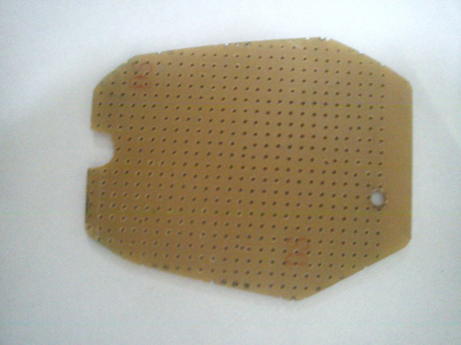
1) We took the internal measurements, cut and filed the PCB to the proper shape, so as to fit in the assembly comfortably.
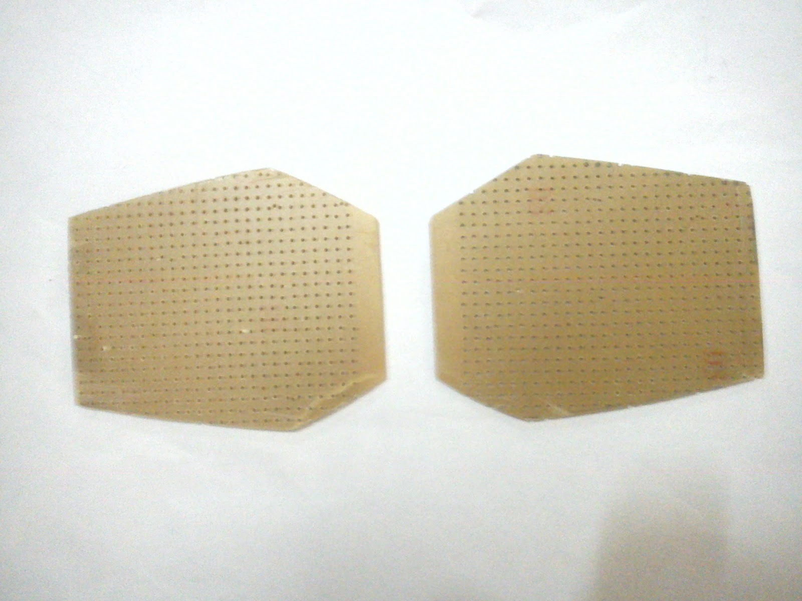
2) We drilled two holes on each PCB for fitting the L- bend and for the screws to holds the assembly firmly.
3) Circuit diagram (LED)

4) Circuit diagram (Bike's output to LED setup converter)

5) The LEDs and Resistors are soldered onto the PCBs according to the circuit diagram.

6) The L- bend is fixed, hence joining both the PCBs in a calculated angle. A bulb connector is soldered with the wires.

7) The connector is placed into the bulb socket and the entire tail lamp section is fixed back.
RESULT:
After a lot of hard work, dedication and patience......


COST: Rs.100(approx)
TAIL LAMP OUTPUT: 1W (STOCK 5W)
BRAKE LAMP OUTPUT: 2W (STOCK 21W)
The entire LED setup is plug n play i.e. it can be removed and replaced by the stock bulb in just 5 minutes. Does not void WARRANTY of the bike.
NOTE: No changes were made in the bike's wiring.
ENJOY THE RIDE!!!
MADE BY:
Arjun Nair
Varun A S
Ananay Sharma
Please Comment!!
Great work buddy.... appreciate the effort :) :)
ReplyDeletebro think abt the light lost by non reflection...
ReplyDeleteThat was considered.. LED's plastics are designed to minimize the loss from the sides.. Most of the light is focused straight ahead, hence LEDs doesn't require reflectors! :)
ReplyDeleteWe had taken care of all the possible real time problems SdM bro :) We ran elaborate tests before making it and fitting it onto the bike.We subjected it to high speed tests, where the probability of technical failure is high, due the the vibrations caused to the circuit and its minor connections. But it came out successfully.30000hrs of working guaranteed.
ReplyDeleteawesome work varun..!!! well done..:)
ReplyDeletereally thoughtful....
ReplyDeleteGreetings! I can notice the fact that you deeply get the sense of what you are writing about here. Do you have a special education that is somehow linked with the subject of the post? Can't wait to see your answer.
ReplyDeleteHey, I am a student doing electronics engineering. But I had just started the course when I did this project. I guess it is just the interest in the subject which drives me.
DeleteGREAT JOB...
ReplyDeleteWorking to Modify with R6 ZF 03-05 R6 03-08 R6S indicator
ReplyDeleteAttach the Light into the internal housing over PCB acting as Base .. Remove the REd housing .. after installation fix the clar cap ..
Cost .. Rs 1000 .. ( Built in Transistors ) less headaches less pain .
Cool. We are working on a new one using SMD LED's.. We are planning to remove the red casing when we install that...
Deletethankss a lot guys...will be doing it shortly...and one thing how did u guys took the measurements to cut the PCB in that shape?
ReplyDeleteWe opened up the casing and made cardboard cutouts for the required shape. You can then refer to the cardboard cutouts to cut the pcb.
DeleteWe opened up the casing and made cardboard cutouts for the required shape. You can then refer to the cardboard cutouts to cut the pcb.
Deletethanks Arjun..by da way if i want to opt for different pattern can i go for it??? if yes,what are the changes that i shall be requiring???
ReplyDeleteYou can make any design of your choice. Just make sure that you don't exceed the current rating of the LED. 30 mA is a good rate.
Deletethanks buddy
DeleteWhat will be the alue of resistors if i use white LEDs?
DeleteThis design works with LED's that have "forward voltage" (For your reference: http://dangerousprototypes.com/docs/Basic_Light_Emitting_Diode_guide#Voltage_drop_or_forward_voltage) under 2.8V. White LEDs typically have forward voltage values over 2.8V (Usually 3.5V). Hence, a complete redesign is required if white LEDs are used. Red, Yellow, Orange and Green LEDs can be swapped without any changes.
DeleteThat's what I asked, what resistor should I connect in series.
Deletemy calculations are for 12V supply 3.5V white LEDs drawing close to 20mA current connecting 3 in series.
[12- (3x3.5)] / [20mA] = resistor value R
that gives 75 ohms. I would take 1/4 watt resistor 100 ohm to be on safer side.
^^^^^ is this correct?
Look I just want resistor value I need to connect with 3 (or if possible 4) LEDs, then I will design the wiring and all by myself, but I can't seem to find the resistor value.
Thanks for reply, need help on this one. :(